Leave Your Message

What Are the Top Types of Base Station Filters?

Base Station Filters control which radio frequencies pass through a cellular site and which are rejected. Their job sounds simple. The engineering is not. A filter must reduce interference while preserving the wanted signal, often inside equipment exposed to changing temperatures, vibration, and high transmit power. Even a small mismatch can affect insertion loss, coverage, or receiver performance.

Common options include cavity, ceramic, dielectric, lumped-element, and combline filters. Cavity designs are known for strong rejection and power handling, but they can be bulky. Ceramic and dielectric filters may save space, though their performance depends on the required frequency range and design. Lumped-element filters suit compact assemblies, while combline structures can offer useful selectivity in a smaller footprint than some cavity designs. There is no universal winner.

The right choice depends on more than a product label. Engineers compare operating bands, bandwidth, insertion loss, isolation, power rating, size, and environmental stability. They also consider whether the site needs a duplexer to separate transmit and receive paths. Details matter. A published specification is a starting point, not proof that a filter will fit every installation. Actual system conditions can expose trade-offs that a brief datasheet cannot show. This guide examines the top types of Base Station Filters, their practical strengths, and the questions worth asking before selection. One point deserves scrutiny: compactness may come at a cost.
What Are the Top Types of Base Station Filters?

Key Criteria for Classifying Base Station Filters

What Are the Top Types of Base Station Filters?
Key Criteria for Classifying Base Station Filters

Classify base station filters by function, frequency range, bandwidth, and construction. Band-pass filters pass a selected channel while reducing unwanted signals. Duplexers separate transmit and receive paths, while cavity, ceramic, and LC designs describe different physical implementations. These categories overlap: a duplexer may use cavity resonators. So, compare the job and the design separately.

Frequency and bandwidth are practical starting points. 3GPP TS 38.104 specifies NR channel bandwidths from 5 to 100 MHz in FR1 and up to 400 MHz in FR2. These figures describe supported radio channels, not a filter’s guaranteed passband. Check the operating band, insertion loss, rejection, power handling, and temperature stability against the station’s actual requirements. A few decibels of extra loss can matter in a high-power transmit path. The right trade-off is not always obvious.

Tips: Request measured response curves, not only a center-frequency rating. Check rejection at nearby bands and confirm performance across operating temperatures. A specification sheet can look convincing, yet omit the conditions behind its measurements.

What Are the Top Types of Base Station Filters? — Key Criteria for Classifying Base Station Filters
Filter Type How It Works Typical Characteristics Common Base Station Uses Key Selection Criteria
Cavity filter Uses one or more resonant metal cavities to pass a selected frequency band and reject signals outside it. Often provides high power handling, low insertion loss, and strong selectivity. Size and weight can be relatively high, especially at lower frequencies. High-power radio paths, macro sites, and applications requiring substantial out-of-band rejection. Passband and rejection requirements, insertion loss, power handling, physical size, temperature stability, and tuning needs.
Ceramic dielectric filter Uses ceramic dielectric resonators to create a band-pass or other frequency-selective response. Can offer a compact form factor and useful selectivity. Performance depends on the ceramic material, resonator design, and operating frequency. Radio-frequency front ends where a balance of size, loss, and selectivity is required. Operating band, insertion loss, bandwidth, rejection, temperature behavior, power rating, and package size.
SAW filter Uses surface acoustic waves on a piezoelectric substrate to provide frequency selection. Compact and suitable for many lower- and mid-frequency applications. Power handling and frequency capability depend on the device design. Compact radio modules and signal paths where size and well-defined band selection are priorities. Center frequency, bandwidth, insertion loss, rejection, power handling, temperature range, and adjacent-band interference requirements.
BAW filter Uses acoustic resonance through the thickness of a piezoelectric structure to filter radio-frequency signals. Can support higher-frequency operation and compact designs, with performance varying by implementation and required bandwidth. Higher-frequency radio paths and compact front ends with demanding selectivity requirements. Frequency band, bandwidth, insertion loss, out-of-band rejection, power handling, thermal stability, and integration constraints.
Waveguide filter Uses resonant sections of a hollow conductive waveguide to pass or reject selected microwave frequencies. Can handle high power and provide low loss at microwave frequencies, but is generally larger and less convenient to integrate than planar components. Microwave and millimeter-wave equipment where power handling or low loss justifies the additional size. Operating frequency, bandwidth, insertion loss, power level, rejection, waveguide dimensions, and installation space.
Duplexer or diplexer assembly Combines multiple filter paths: a duplexer separates transmit and receive bands, while a diplexer routes different frequency bands through shared ports. This is a filter arrangement rather than a single resonator technology. Isolation between paths and total insertion loss are central performance measures. Shared antenna paths, frequency-division duplex systems, and equipment that routes distinct bands through common connections. Band separation, transmit-to-receive isolation, insertion loss, power handling, intermodulation performance, and port configuration.
Note: Frequency coverage, bandwidth, loss, rejection, and power handling are design-dependent; no single technology has a universal operating range. Compare filters against the radio system’s band plan, required selectivity, transmit power, environmental limits, and available space.

Cavity Filters for High-Power Signal Separation

Cavity filters are common in base stations that must separate strong transmit signals from sensitive receive channels. Each filter uses hollow metal resonators to favor a narrow frequency range and reject unwanted energy. In a duplexing setup, this selectivity helps transmit and receive paths share an antenna without overwhelming the receiver. The exact spacing between bands matters.

Their rigid cavities can handle substantial RF power, but “high power” depends on the design. A filter’s rating, insertion loss, connector quality, and cooling conditions all affect performance. Even a small amount of loss becomes heat. In a cabinet exposed to summer sun, that heat can shift tuning or shorten component life if airflow is poor. Heat still matters.

Technicians typically check passband response, rejection, and return loss during installation and maintenance. A spectrum analyzer can reveal whether nearby signals are leaking into the desired channel, while a temperature check may expose a separate problem. Cavity filters can also be larger and heavier than compact alternatives, and precise tuning takes care. Field adjustments are not always easy. A clean test result at room temperature does not guarantee identical behavior on a hot rooftop; that detail is easy to overlook.

What Are the Top Types of Base Station Filters?

Cavity filters for high-power signal separation across common cellular frequency ranges

Cavity filters are commonly used in base stations to pass selected frequency bands while rejecting unwanted signals. The ranges shown are illustrative combined uplink/downlink allocation spans; allocations vary by region, and each filter’s passband is designed for its specific deployment.

Ceramic and Dielectric Filters for Compact Designs

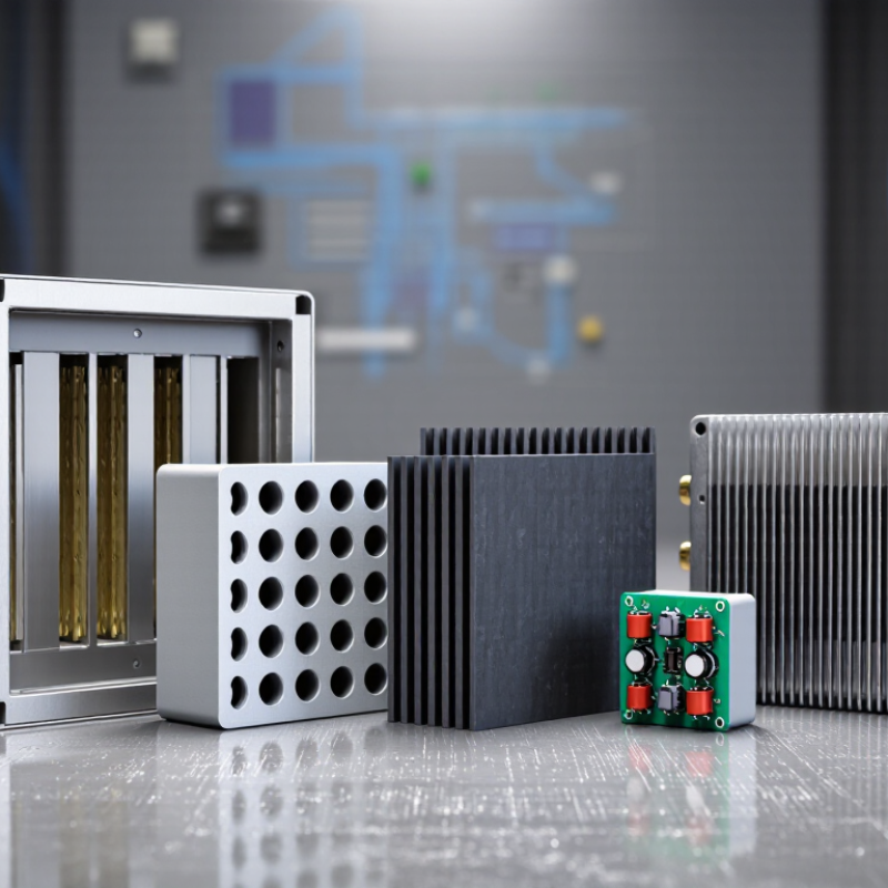
Ceramic and dielectric filters suit base stations where every millimeter of rack or radio space matters. Their resonant structures can provide useful frequency selectivity without the bulky cavities used in some high-power systems. That helps. Smaller assemblies can simplify placement near amplifiers and antennas, although compact packaging leaves less room for heat and tuning adjustments.

Many ceramic filters use piezoelectric resonators, while dielectric-resonator filters use high-permittivity ceramic materials to confine electromagnetic energy. Both approaches can support compact designs, but their performance depends on the chosen frequency band, insertion loss, bandwidth, and power level. Cavity filters may remain preferable when power handling or narrow selectivity outweighs size. Small is not simple.

A practical comparison should include more than filter dimensions. Engineers can check passband loss, rejection of nearby signals, temperature stability, and how the filter behaves beside other components. On a densely packed radio board, even a small layout change may affect coupling or matching. Enclosure temperature can also shift performance. Bench measurements help reveal these issues, yet a prototype may not fully represent a finished outdoor unit. That limitation deserves attention during selection.

SAW and BAW Filters for Precise Frequency Selection

What Are the Top Types of Base Station Filters?

SAW and BAW Filters for Precise Frequency Selection

Base stations handle several radio bands, so filters must pass wanted signals while reducing nearby interference. Surface acoustic wave (SAW) filters use electrical signals to create acoustic waves along a piezoelectric surface. Their resonant behavior helps define a narrow frequency range. In practical designs, engineers assess insertion loss and rejection together; a sharp filter is less useful if it weakens the wanted signal too much.

Bulk acoustic wave (BAW) filters create vibrations through the thickness of a piezoelectric layer. This structure can support precise selection at higher frequencies, with compact components suited to dense radio equipment. SAW and BAW are not interchangeable labels for “better” performance. Their useful ranges overlap, and the right choice depends on operating band, bandwidth, power handling, temperature stability, and available space. The trade-off is real.

During design, engineers also consider how filters behave alongside amplifiers, antennas, and neighboring transmit paths. A filter that looks suitable on a component sheet may respond differently in the assembled radio, where heat and layout matter. Measurements across the intended frequency band help verify actual loss and isolation. There is no universal winner. The best selection is the one that meets the station’s measured requirements without adding unnecessary complexity.

Comparing Filter Types Across Base Station Applications

What Are the Top Types of Base Station Filters?

Filter choice depends on the radio’s power, operating bands, and available space. Cavity filters use resonant metal chambers to provide strong selectivity and handle substantial power. They suit many macro base stations, though their size and weight can complicate installation. Ceramic filters are smaller and lighter, making them useful where equipment space is limited. Their performance depends on the design and frequency range, so compact does not always mean better.

Surface acoustic wave and bulk acoustic wave filters can support compact radio designs, particularly at higher frequencies. They may be a practical fit for small cells or tightly integrated radio units, but power handling and insertion loss need careful review. LC filters offer design flexibility and can be useful in less demanding filtering stages. There is no perfect pick. Real deployments can expose trade-offs that a clean specification sheet misses.

Tips: Compare insertion loss, rejection, bandwidth, and power handling at the actual operating frequencies. Check temperature stability and connector layout, too. If possible, evaluate the filter with the radio hardware; a small mismatch can affect system performance.