
When a global buyer evaluates telecom hardware, attention often goes to antennas, radios, and visible network equipment. Yet Base Station Filters quietly determine how cleanly a site handles nearby signals. These components reject unwanted frequencies and protect receiver sensitivity. A well-matched filter can reduce interference, stabilize coverage, and support consistent service in crowded bands. The difference may appear small on paper. It becomes obvious beside a rural tower or dense urban rooftop. Engineers see it through fewer alarms, cleaner measurements, and fewer unexplained performance drops. Buyers experience it through fewer replacements and more predictable maintenance.
For international procurement teams, filter selection is not simply a price comparison. Frequency range, insertion loss, rejection, power rating, connector type, environmental sealing, and tuning tolerance all deserve verification. Test reports should identify methods, sample conditions, and measurement dates. Certifications and traceable quality records also help buyers assess supplier reliability across borders. A supplier that answers technical questions clearly may be more valuable than one offering the lowest quote. Still, specifications alone can mislead. A polished datasheet is not proof of field performance. Installation errors, changing band plans, and harsh weather may expose weaknesses later. Good buyers request samples, inspect markings, confirm compatibility, and discuss after-sales support before approval. The process is not flawless. It depends on honest data and careful review. Understanding Base Station Filters therefore helps global buyers control risk and pursue dependable, long-term network value.

Base station filters are RF components that separate wanted signals from unwanted energy. They use resonant cavities, dielectric materials, or surface acoustic wave structures. Their job is precise: pass selected frequencies and reject nearby interference. Duplexers also let transmit and receive paths share one antenna. This reduces hardware space and limits self-interference.
A filter’s key measures include insertion loss, rejection, bandwidth, and passive intermodulation performance. Lower insertion loss helps preserve transmitter power. Strong rejection protects nearby networks, especially in crowded urban sites. The Ericsson Mobility Report, June 2024, estimated 2.6 billion 5G subscriptions by the end of 2023. It projects about 6.3 billion by 2029. More connected users mean denser spectrum use. Small weaknesses become expensive problems.
Not every specification tells the whole story. A filter may perform well in a laboratory, yet drift under heat, moisture, vibration, or poor connector assembly. Buyers should request test conditions, frequency tolerances, and PIM results. They should also verify compatibility with local band plans and 3GPP requirements. The ITU’s Global Trends in Connectivity report highlights continuing growth in mobile broadband demand, but coverage quality still varies widely. That makes one universal filter design unrealistic.
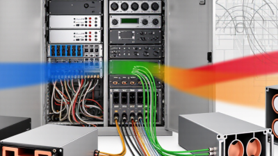
Base station filters are essential because they control which radio signals enter and leave the system. Without proper filtering, nearby frequencies can create interference, reduce coverage, and weaken voice or data quality. In dense urban areas, this problem becomes visible quickly. A receiver may show unstable performance even when the antenna and power amplifier appear healthy.
A well-designed filter provides frequency selectivity and strong isolation between channels. It also limits unwanted emissions, protects sensitive components, and supports more predictable network operation.
Buyers should examine insertion loss, rejection levels, power handling, temperature stability, and connector quality. These specifications should match the deployment environment, not only the catalog requirements.
Field experience shows that small losses can become significant across long feeder runs. That detail is easy to overlook. Testing reports, traceable measurements, and compliance documents also help buyers compare suppliers with greater confidence.
Still, specifications do not tell the entire story. Installation errors, moisture, aging, and poor maintenance can reduce filter performance. I have seen technically suitable components underperform because the housing was exposed to harsh weather. A careful purchasing process should therefore include sample testing, environmental verification, and clear support terms. Reliability is built through evidence, not attractive claims.
Global buyers need to match base station filters with local spectrum plans, network architecture, and site conditions. A bandpass filter allows a defined frequency range while reducing unwanted signals outside it. This is the everyday choice for many radio paths. Cavity filters are useful when operators need strong selectivity and stable performance under high transmit power. They are large, but dependable.
Duplexers separate transmit and receive signals while using one antenna system. This can reduce installation space, especially on crowded towers. Diplexers combine or separate different frequency bands, helping one feeder support multiple services. Notch filters suppress a specific interfering signal, such as a nearby carrier or strong public-safety transmission. Waveguide filters may suit microwave links, where low loss and weather resistance are critical.
Specifications deserve close review. Check passband, rejection, insertion loss, power handling, impedance, connector type, and PIM performance. A filter that works well in a laboratory may perform differently after years of rain, heat, dust, and vibration. Regional approvals also matter, because frequency allocations and safety requirements vary by market. Buyers should request test reports and environmental ratings, not only catalog figures.
One assumption often fails: more rejection is not always better. Excessive filtering can increase signal loss and reduce coverage. Engineers should compare measured data with the planned link budget. Sometimes, the cheaper option creates more field work. That lesson is easy to overlook.
Why Do Base Station Filters Matter for Global Buyers?
Base station filters directly shape network quality, regulatory compliance, and operating costs. In field deployments, a poorly selected filter can raise insertion loss, weaken coverage, and increase dropped calls. A well-matched filter suppresses unwanted signals before they disturb sensitive receivers. This matters as traffic rises. The Ericsson Mobility Report, June 2024, forecasts mobile data traffic will grow about 20% annually through 2029. More traffic leaves less room for interference.
Compliance is equally practical. Filters must support required emission limits, frequency separation, and coexistence conditions under applicable 3GPP and regional rules. A filter may pass laboratory tests yet perform poorly beside a high-power neighboring transmitter. Buyers should request measured rejection, return loss, insertion loss, power handling, and temperature stability. Small details matter. GSMA Intelligence’s The Mobile Economy 2024 reports more than 5 billion mobile internet users worldwide, increasing pressure on dense networks and shared spectrum.
Costs appear beyond the purchase order. Higher insertion loss can force additional transmit power, while weak environmental protection can trigger repeated tower visits. Over time, maintenance may cost more than the filter itself. However, specifications are not always complete. Installation quality, cable routing, and connector torque can change real results. That deserves honest attention. Global buyers should compare independent test evidence, warranty terms, local certification support, and lifecycle data rather than choosing only the lowest unit price.
A practical procurement comparison of key RF filter specifications for multi-region base-station deployments.
| Evaluation Dimension | Typical Procurement Benchmark | Effect on Network Quality | Compliance and Deployment Relevance | Cost and Lifecycle Consideration |
|---|---|---|---|---|
| Operating Frequency | 700–900 MHz; 1,710–2,690 MHz; 3,300–3,800 MHz | Correct band alignment reduces out-of-band loss and supports stable coverage, capacity, and receiver sensitivity. | Frequency allocation differs by country; the filter passband must match the licensed spectrum and local channel plan. | Multi-band or wideband designs can simplify inventory, while highly customized band plans may increase engineering and stocking costs. |
| Insertion Loss | Typically ≤ 0.5 dB for a well-matched passive filter assembly | Lower loss preserves transmit power and receiver sensitivity. A 0.5 dB loss represents approximately 11% power reduction. | Helps equipment remain within link-budget and radiated-power limits without requiring unplanned amplifier adjustments. | Lower-loss materials, larger cavities, and tighter manufacturing tolerances may raise purchase cost but can reduce energy consumption. |
| Return Loss / VSWR | Return loss ≥ 20 dB; VSWR approximately ≤ 1.22:1 | Good impedance matching reduces reflected power, thermal stress, and signal distortion in the RF chain. | Supports conformance testing and helps maintain stable operation across temperature, frequency, and power variations. | Precision tuning and factory test data may add initial cost, but they reduce field troubleshooting and retuning expenses. |
| Out-of-Band Rejection | Approximately 50–80 dB at specified offset frequencies | Limits interference from neighboring bands, harmonics, and co-located radio systems, improving throughput and call reliability. | Important for spectrum-emission limits and coexistence requirements; the required rejection must be checked against the national frequency plan. | High-rejection designs may require additional resonators or filtering stages, increasing size, weight, and unit price. |
| Passive Intermodulation (PIM) | ≤ −150 dBc under a defined two-tone test, with high-performance assemblies often specified near −153 dBc | Low PIM protects the receiver noise floor and reduces uplink desensitization, especially in high-power, multi-carrier sites. | Test conditions must be stated, including tone spacing, power level, connectors, cable assembly, and measurement method. | Higher-grade contacts, plating, assembly control, and PIM screening increase upfront cost but can reduce site visits and service interruptions. |
| Power Handling | Common passive RF assemblies: 100–500 W average power, subject to frequency and duty cycle | Correct power rating prevents thermal drift, arcing, compression, and premature component failure. | Purchasers should verify continuous-wave and peak-power ratings, especially for multi-carrier and 5G deployments. | Higher power capability may require larger conductors, improved heat dissipation, and stronger connectors, increasing material and logistics costs. |
| Group Delay Variation | Often targeted below 10–20 ns across the defined passband, depending on application | Low variation helps preserve modulation quality and reduces distortion in wideband and multi-carrier signals. | Particularly relevant when filters are used in carrier aggregation, wideband radio paths, or tightly synchronized networks. | Tighter delay control can require more complex filter structures and additional production testing. |
| Environmental Protection | Outdoor assemblies commonly specified at IP65 or higher; typical operating range −40°C to +85°C | Sealing and temperature stability help maintain RF performance during rain, dust, icing, solar heating, and daily thermal cycling. | Outdoor deployment requirements should be checked against IEC 60529 ingress protection and applicable environmental test procedures such as IEC 60068. | Weatherproof housings and environmental testing increase purchase cost but reduce corrosion, water ingress, and replacement risk. |
| Connector and Interface Compatibility | Interface must match the radio and feeder system; common options include 4.3-10, 7/16 DIN, and N-type families | Correct interfaces reduce mismatch loss, mechanical stress, and installation errors. | Connector choice affects safety, ingress protection, PIM performance, and local installation practices. | Using an existing site interface can lower adapter, labor, and spare-parts costs; nonstandard interfaces may increase deployment complexity. |
| Regulatory and Technical Evidence | Request datasheets, calibration records, PIM reports, environmental test results, and traceable quality documentation | Verified data reduces the risk of deploying filters that fail to meet link-budget or interference assumptions. | Depending on the market, buyers may need evidence related to radio-equipment conformity, EMC, safety, environmental restrictions, and operator acceptance. | Complete documentation reduces customs delays, qualification rework, and costly post-installation validation. |
| Lead Time and Spares | Plan for project-specific qualification plus operating spares; lead time varies by tuning and volume | Availability of compatible replacements helps maintain network uptime during failures or expansion projects. | Global buyers should confirm whether the same electrical and mechanical specification is available across all target regions. | Standardized filter families can reduce inventory complexity, freight cost, and emergency procurement premiums. |
| Total Cost of Ownership | Evaluate purchase price together with energy loss, installation labor, testing, maintenance, and replacement risk | Filters with stable RF performance can reduce dropped connections, interference investigations, and network optimization work. | Compliance-ready products lower the risk of failed acceptance tests, deployment delays, and regional requalification. | A lower unit price may be outweighed by higher insertion loss, poor PIM performance, short service life, or limited documentation. |
Global buyers should assess suppliers beyond price and catalog range. Base station filters control unwanted signals, protect receivers, and support stable network performance. Ericsson’s Mobility Report forecasts mobile data traffic will continue growing strongly through 2029, increasing pressure on radio networks and spectrum efficiency. A weak filter can become a costly bottleneck.
Check the supplier’s frequency coverage first. Confirm passband, rejection, insertion loss, group delay, and power handling under real operating conditions. Ask for measured test reports, not only typical values. Passive intermodulation results matter, especially near dense antenna sites. Also verify operating temperature, humidity resistance, connector quality, and enclosure protection. Small parts. Large consequences.
A reliable supplier should provide traceable serial numbers, calibration records, and consistent production samples. Review quality systems, inspection procedures, warranty terms, and replacement timelines. GSMA’s Mobile Economy 2024 reports about 5.6 billion unique mobile subscribers worldwide in 2023, showing how widely network equipment is deployed. This scale makes supply continuity important. Regional certifications and documentation should match the destination market. Do not assume one approval works everywhere. A polished datasheet can still hide weak testing. Buyers should request independent validation when specifications affect safety, coverage, or long-term operating costs.