What Is a Base Station Filter and How Does It Work?
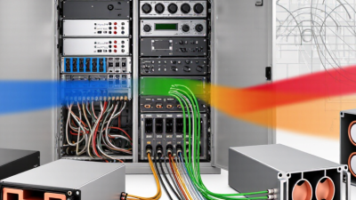
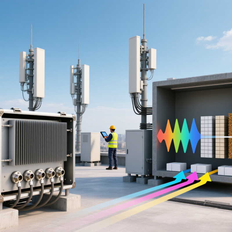
Base Station Filters are essential RF components in modern cellular networks. They help a base station transmit and receive signals within assigned frequency ranges. At a busy rooftop site, several antennas may operate only meters apart. Without careful filtering, strong nearby signals can disturb weaker channels.
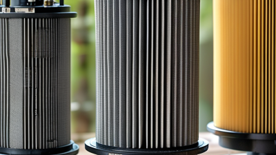
These filters work through controlled electrical resonance. A cavity, ceramic, or surface acoustic wave structure allows selected frequencies to pass. It attenuates unwanted energy outside the intended band. Engineers evaluate insertion loss, rejection, isolation, bandwidth, and power handling before deployment. These measurements affect coverage, equipment temperature, and long-term reliability.
In practical installations, technicians connect test equipment and inspect signal traces during commissioning. They may find unexpected interference from neighboring systems, aging connectors, or imperfect antenna alignment. Small details matter.
Filter performance is not determined by frequency response alone. Physical size, weather sealing, thermal behavior, and connector quality also influence field results. A filter that performs well in a laboratory may require adjustment on a crowded tower. That assumption can be wrong.
Understanding how Base Station Filters work makes network planning more precise. It also helps readers compare filter types for macro sites, small cells, and private networks. Reliable decisions depend on manufacturer specifications, measured data, and the operating environment. No single filter suits every deployment. That is worth remembering.
Definition and Role of a Base Station Filter
A base station filter is a radio-frequency device that controls which signals enter or leave a cellular base station. It allows selected frequency bands to pass while reducing unwanted energy. Its main role is interference control. Without filtering, nearby transmitters could disturb sensitive receivers. The result may include dropped connections, reduced coverage, or noisy measurements.
The filter sits between the radio equipment and the antenna system. In the transmit path, it suppresses unwanted harmonics and out-of-band emissions. In the receive path, it blocks strong signals that could overload the receiver. Many filters use tuned cavities or resonant circuits inside a metal enclosure. Their performance is measured through insertion loss, rejection, return loss, and isolation. Small losses matter. Even a few extra decibels can reduce useful coverage.
A practical inspection often includes checking connectors, feeder cables, temperature, and tuning stability. Moisture or loose connections can change performance. Engineers also compare measured values with the site design before replacing a filter. A simple definition can hide these trade-offs. Stronger rejection may increase insertion loss, so the “best” filter depends on the network’s frequency plan. No filter is perfect. Its real value comes from controlled performance, correct installation, and regular verification.
Main Types of Filters Used in Base Station Systems
A base station filter controls which radio frequencies enter or leave a communication system. It reduces unwanted energy, protects receivers, and limits interference between nearby channels. In a working site, this can mean clearer calls, steadier data, and fewer alarms. Filters do not create signal strength. They preserve useful performance.
Bandpass filters are widely used because they allow a selected frequency range to pass. A cavity bandpass filter uses resonant metal chambers and can handle high power with low loss. Duplexers combine transmitting and receiving paths through carefully spaced frequency bands. This arrangement supports simultaneous transmission and reception through one antenna system. Notch filters do the opposite in a narrow region. They reject a troublesome frequency, such as a strong nearby transmitter. Low-pass and high-pass filters remove energy above or below a defined limit. Each type suits a different interference problem.
Modern systems may also use compact ceramic, surface-acoustic-wave, or bulk-acoustic-wave filters. These options save space, although their power handling and thermal limits require careful review. Engineers usually check insertion loss, return loss, rejection, isolation, and passive intermodulation during testing. Temperature changes can shift performance slightly. So can loose connectors, moisture, or aging components. A filter that looks excellent on paper may perform poorly after installation. Field measurements with calibrated equipment remain essential. No filter is perfect. Designing only for nominal frequency can be a costly mistake.
How a Base Station Filter Processes Radio Signals
What Is a Base Station Filter and How Does It Work?
How a Base Station Filter Processes Radio Signals
A base station filter is a passive device that controls radio frequencies inside a mobile communication site. Its job is simple: allow wanted signals through and reduce unwanted energy. The device does not decode messages. Instead, it shapes the signal by frequency.
On the transmit path, the filter removes harmonics and out-of-band noise before the antenna radiates. On the receive path, it blocks nearby interference before the receiver handles weak signals. This separation protects sensitive circuits from strong, unwanted transmissions. A duplexer can also let transmitting and receiving signals share one antenna while maintaining isolation.
Engineers evaluate filters through insertion loss, return loss, rejection, and bandwidth. A cavity filter, for example, uses carefully tuned resonant chambers to select a narrow frequency range. During installation, technicians connect test equipment and compare measured values with site requirements. Even a small connector problem can change performance. Real sites are rarely perfect. Temperature, moisture, cable movement, and aging can shift the response slightly.
A filter may reduce signal power as well as interference. That trade-off matters. Excessive insertion loss can weaken coverage and increase equipment workload. If a nearby transmitter creates unexpected noise, engineers may inspect the spectrum, check grounding, and retune the filtering network. The ideal response on a test screen may not survive field conditions. Careful measurements and documented maintenance remain essential for reliable radio performance.
What Is a Base Station Filter and How Does It Work?
How a Base Station Filter Processes Radio Signals
This representative RF response profile shows how a band-pass filter centered at 1842.5 MHz allows the intended downlink band to pass with low insertion loss while increasingly attenuating signals farther from the operating frequency. The response helps reduce interference, protect radio equipment, and improve spectrum isolation.
Key Components and Performance Specifications
A base station filter separates wanted radio signals from unwanted energy. It protects receivers from nearby carriers, harmonics, and external interference. Inside the enclosure, resonant cavities or ceramic elements create a controlled frequency path. The filter passes the assigned band and sharply attenuates signals outside it.
Key components include resonators, coupling structures, connectors, tuning screws, and a weather-resistant housing. Engineers usually evaluate insertion loss, return loss, rejection, bandwidth, power handling, and passive intermodulation. Insertion loss matters because every lost decibel reduces link efficiency. Return loss shows how well the filter matches the transmission line. High rejection is essential when neighboring bands sit close together. Passive intermodulation must remain very low, often below -153 dBc in demanding configurations.
The figures need context. 3GPP TS 38.104 defines radio transmission and reception requirements for NR base stations, including unwanted emissions and receiver performance. ITU-R M.2410 identifies 20 Gbit/s downlink peak data rate, 1 ms radio latency, and one million connections per square kilometer for IMT-2020 scenarios. These targets increase pressure on filtering accuracy. Thermal stability also matters. A cavity filter may shift slightly as metal expands during heavy transmission. Small shifts can affect rejection.
Field experience reveals an uncomfortable detail. A filter can pass factory testing and still perform poorly after installation. Loose connectors, water ingress, or cable stress may change results. Specifications alone are not enough. Engineers should verify sweep data, temperature behavior, PIM performance, and installation torque. That extra discipline is often overlooked.
Installation, Maintenance, and Common Applications
A base station filter controls unwanted radio-frequency energy before it reaches sensitive equipment. It allows selected channels to pass while reducing interference from nearby transmitters. This keeps receivers clearer and protects amplifiers from excessive signals.
Installation begins with the frequency plan.
Technicians should confirm passband, rejection, power rating, and insertion loss before connecting the filter. Mount it close to the radio equipment, but leave enough space for inspection and airflow. Use suitable coaxial cables, weatherproof connectors, and a properly bonded ground. Tighten connections to the specified torque. Small errors matter. A loose connector can create heat, signal loss, or passive intermodulation. After installation, a sweep test can verify return loss and filter performance. Record the results for future comparison.
Maintenance should include visual checks for corrosion, water entry, loose hardware, and damaged cable jackets.
Remote sites need special attention after storms or temperature changes. Measure insertion loss during scheduled service, especially when coverage becomes inconsistent. Clean connectors carefully and replace damaged sealing materials. Keep an inspection log with dates, readings, and corrective work. In practice, maintenance schedules are sometimes too optimistic. Dust, vibration, and aging seals can change performance earlier than expected.
These filters support cellular networks, private radio systems, emergency communication sites, and industrial facilities. They are also useful where several transmitters share a tower or shelter. A filter may solve interference, but it cannot correct poor antenna alignment or an unsuitable frequency plan. Technicians should evaluate the complete RF path.