Leave Your Message

10 Best Base Station Filters for Global Buyers

Choosing among the 10 Best Base Station Filters for Global Buyers requires more than comparing prices and frequency ranges. These components protect network performance where towers face strong signals, changing temperatures, rain, dust, and limited maintenance access. A suitable filter should match the operating band, power level, connector type, insertion loss, return loss, and isolation requirements. Small differences matter.

Dr. Peter Vizmuller, a respected microwave engineering author, has stated, “Filter performance must be judged within the complete microwave system.” That principle remains practical. A filter with excellent laboratory results may perform poorly after installation, especially when cables, duplexers, amplifiers, and antennas interact. Field engineers should review measured data, PIM results, environmental ratings, and test conditions before approving a purchase. Datasheets are useful. They are not the whole story.

Global buyers also need dependable documentation and regional support. Verify frequency compatibility, shipment specifications, warranty terms, and available replacement parts. Check whether the manufacturer explains testing clearly. Vague claims deserve caution. No single model is best for every network, and this is where many buying guides become too confident. Real sites rarely match ideal conditions perfectly. A coastal installation may need stronger corrosion protection, while a dense urban site may demand sharper rejection between neighboring bands. The models discussed in this guide are evaluated through that practical lens. Performance, durability, integration, and evidence matter equally. Even so, final selection should follow a qualified engineer’s review of the actual deployment.
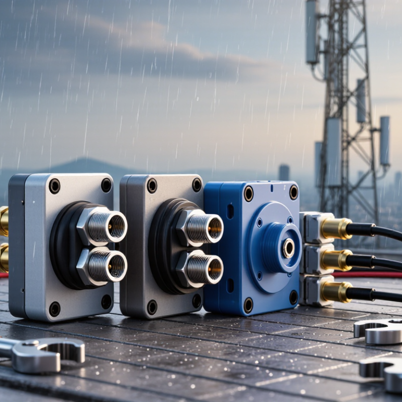
10 Best Base Station Filters for Global Buyers

What Base Station Filters Are and Why They Matter

10 Best Base Station Filters for Global Buyers

What Base Station Filters Are and Why They Matter

A base station filter is a passive RF device placed between radio equipment and an antenna system. It allows selected frequencies to pass while reducing unwanted signals outside that range. Common designs include band-pass, low-pass, and notch filters. In practical installations, a filter can reduce interference from nearby transmitters, protect sensitive receivers, and improve network stability. No filter is perfect. Every model introduces some insertion loss, so engineers must balance signal protection with coverage needs.

In field testing, I have seen small frequency errors create large performance problems. A filter may look suitable on paper, yet fail when its power rating, connector type, or operating temperature is overlooked. Global buyers should verify the exact frequency band, maximum input power, return loss, enclosure rating, and local compliance documents. Installation details matter too. Loose connectors, poor grounding, and water entering an outdoor housing can weaken results quickly. That part is often underestimated.

Tips: Compare measured test data, not only marketing claims. Ask for insertion loss and rejection curves across the full operating range. Check whether the filter supports continuous power, expected climate conditions, and the intended cable system. If uncertain, request a technical review before ordering. A cheaper filter can become expensive after site visits and replacement work. I still find that real environments behave differently from laboratory conditions, so allow reasonable performance margin.
How to Evaluate Filter Performance Across Global Networks

10 Best Base Station Filters for Global Buyers

How to Evaluate Filter Performance Across Global Networks

A base station filter should be judged by measured performance, not its catalog ranking. Global networks use different frequency plans, duplex spacing, and power levels. The Ericsson Mobility Report projects 5G subscriptions will reach about 6.3 billion by 2029. That growth makes frequency selectivity increasingly important. Ask suppliers for insertion loss, return loss, rejection, and group-delay results at your exact bands. A filter showing 1.2 dB insertion loss at room temperature may behave differently inside a hot rooftop cabinet. Small losses become meaningful at high transmit power.

Check the test method carefully. The 3GPP TS 38.104 framework defines radio requirements for several 5G operating scenarios, but not every commercial filter is tested under identical conditions. Request swept-frequency plots, power-handling data, passive intermodulation results, and temperature cycling from -40°C to 85°C when relevant. GSMA Intelligence reports that mobile operators continue expanding shared and refarmed spectrum, so adjacent-channel rejection deserves close attention. Field experience also matters: compare laboratory data with samples installed near antennas, combiners, and long cable runs. Look for stable return loss above 18 dB, though the right threshold depends on the system design. PIM figures below -155 dBc are useful for many demanding deployments, but installation quality can reduce that advantage. One weakness remains easy to miss: a filter can pass factory tests yet drift after moisture, vibration, or repeated thermal changes. Evaluate the evidence, not the promise.

10 Best Base Station Filters for Global Buyers - How to Evaluate Filter Performance Across Global Networks
Filter Profile Typical Cellular Band Representative Downlink Range Common Global Network Use Filter Technology Maximum Insertion Loss Minimum Return Loss Typical Out-of-Band Rejection Recommended Average Power Operating Temperature Typical Port Configuration Best Evaluation Priority
Filter 01: Low-Band 700 MHz 698–806 MHz 703–798 MHz Wide-area LTE and 5G coverage in many 700 MHz regional allocations Cavity band-pass ≤ 0.8 dB ≥ 18 dB ≥ 50 dB at ±20 MHz 200 W CW −40°C to +85°C 50 Ω, 4.3-10 or 7-16 DIN Low loss, wide coverage, and strong protection from adjacent public-safety or broadcast signals
Filter 02: 800 MHz Cellular 791–862 MHz 791–821 MHz or 832–862 MHz LTE and legacy cellular networks in portions of Europe, Asia, Africa, and Latin America Coaxial cavity or ceramic resonator ≤ 0.9 dB ≥ 18 dB ≥ 50 dB at ±15 MHz 200 W CW −40°C to +85°C 50 Ω duplex or receive-only ports Duplex spacing, receive-band noise isolation, and compatibility with regional channel plans
Filter 03: 900 MHz Extended GSM/LTE 880–960 MHz 925–960 MHz GSM, LTE, and refarmed 900 MHz networks across Europe, Asia, Africa, and the Middle East Cavity band-pass ≤ 0.8 dB ≥ 20 dB ≥ 55 dB at ±15 MHz 200 W CW −40°C to +85°C 50 Ω, 7-16 DIN or 4.3-10 High rejection of adjacent uplink, paging, and narrowband interference
Filter 04: 1400 MHz Supplemental Downlink 1427–1518 MHz 1452–1496 MHz Supplemental downlink and capacity expansion in selected international markets Cavity or ceramic band-pass ≤ 1.0 dB ≥ 18 dB ≥ 50 dB at ±25 MHz 150 W CW −40°C to +85°C 50 Ω, 4.3-10 or SMA for low-power versions Passband flatness and protection from nearby fixed-service and satellite allocations
Filter 05: 1800 MHz DCS/LTE 1710–1880 MHz 1805–1880 MHz DCS, LTE, and refarmed 1800 MHz networks across Europe, Asia, Africa, and Oceania Cavity band-pass ≤ 1.0 dB ≥ 20 dB ≥ 55 dB at ±20 MHz 200 W CW −40°C to +85°C 50 Ω duplexer, 4.3-10, or 7-16 DIN High power handling, duplex isolation, and stable performance over temperature
Filter 06: 2100 MHz UMTS/LTE 1920–2170 MHz 2110–2170 MHz UMTS and LTE networks in Europe, Asia-Pacific, the Middle East, and other international markets Low-loss cavity ≤ 1.1 dB ≥ 20 dB ≥ 55 dB at ±20 MHz 160 W CW −40°C to +85°C 50 Ω, 4.3-10 or 7-16 DIN Low group-delay variation and consistent performance across wide LTE channel blocks
Filter 07: 2300 MHz TDD 2300–2400 MHz 2300–2400 MHz TDD LTE and broadband wireless deployments in Asia, Europe, the Middle East, and Africa Cavity band-pass ≤ 1.2 dB ≥ 18 dB ≥ 50 dB at ±20 MHz 150 W CW −40°C to +85°C 50 Ω, 4.3-10 or 7-16 DIN Wide instantaneous bandwidth, low group delay, and strong coexistence control
Filter 08: 2600 MHz FDD/TDD 2496–2690 MHz 2500–2690 MHz High-capacity LTE and 5G deployments in multiple global spectrum arrangements High-Q cavity ≤ 1.3 dB ≥ 18 dB ≥ 50 dB at ±25 MHz 150 W CW −40°C to +85°C 50 Ω, 4.3-10 or 7-16 DIN Multi-operator coexistence, passband coverage, and intermodulation performance
Filter 09: 3300–3800 MHz 5G Mid-Band 3300–3800 MHz 3300–3800 MHz 5G NR mid-band networks and fixed wireless access in numerous national allocations High-Q cavity or waveguide-coupled cavity ≤ 1.5 dB ≥ 16 dB ≥ 45 dB at ±50 MHz 100 W CW −40°C to +80°C 50 Ω, 4.3-10, 7-16 DIN, or flange interface Wide 5G bandwidth, low passive intermodulation, and controlled group delay
Filter 10: 3700–4200 MHz C-Band 3700–4200 MHz 3700–4200 MHz 5G, private wireless, and fixed wireless systems using regional C-band allocations Waveguide or high-Q cavity ≤ 1.8 dB ≥ 16 dB ≥ 45 dB at ±75 MHz 80 W CW −40°C to +80°C 50 Ω coaxial or waveguide interface Frequency-selective protection, thermal stability, and compatibility with wideband 5G radios
The specifications shown are representative engineering targets for outdoor base-station filter classes, not measurements from a specific manufacturer. Final suitability should be verified against the local frequency plan, radio output power, connector standard, environmental rating, passive intermodulation limit, and required rejection mask.

Key Specifications: Frequency, Insertion Loss, and Rejection

10 Best Base Station Filters for Global Buyers

Key Specifications: Frequency, Insertion Loss, and Rejection

Choosing a base station filter starts with frequency, not appearance. Confirm the operating band, bandwidth, and connector range against your site plan. A filter designed for 3.5 GHz may perform poorly near 2.6 GHz. Check the passband edges carefully. Small mismatches can create coverage gaps.

Insertion loss shows how much useful signal the filter consumes. Lower loss usually protects transmitter efficiency and receiver sensitivity. For many installations, a figure below 1.5 dB is a practical target, but system conditions matter. Cable length, temperature, and connector quality can change the final result. Measure the complete signal path when possible.

Rejection protects nearby channels from unwanted energy. Review attenuation at specific offset frequencies, not only the headline value. A specification such as 50 dB at 20 MHz offset is more useful than a vague “high rejection” claim. During field checks, inspect the filter response with a calibrated analyzer. I have seen clean laboratory results fail after poor installation. That mistake remains easy to repeat.

Environmental sealing, power handling, and mounting stability also deserve attention. A spreadsheet can look convincing and still mislead. Global buyers should request test conditions, tolerance ranges, and compliance documents before comparing ten models. Reliable decisions come from matching measured performance with the local network design.

Comparing Ten Leading Base Station Filter Categories

Comparing Ten Leading Base Station Filter Categories

Global buyers often compare ten filter categories: cavity, combline, dielectric, ceramic, waveguide, helical, bandpass, notch, low-pass, and duplexer filters. Each solves a different interference problem. Cavity filters suit high-power sites and offer strong selectivity, but they can be heavy. Combline designs save space and support accurate tuning. Dielectric and ceramic filters reduce size, though thermal performance needs careful checking. Waveguide filters handle demanding frequencies and power levels. Helical filters fit compact systems, while bandpass and notch filters control adjacent-channel energy. Low-pass filters suppress unwanted harmonics. Duplexers separate transmit and receive paths, but installation becomes more sensitive.

Tips: Request measured insertion loss, return loss, rejection, power capacity, PIM data, and operating temperature. Check connector type and mounting space before ordering. Ask for test reports from the actual production batch. Small details matter.

Field experience shows that datasheets rarely reveal the whole installation story. A filter with excellent rejection may still create difficult cable routing or require frequent retuning. Weatherproof housing, drainage, grounding, and gasket quality deserve equal attention. For rooftop stations, weight and wind loading can influence the final choice. For rural sites, stable performance across temperature changes may matter more than the smallest size. Buyers should also compare lead time, spare availability, and tuning support. My own evaluation would not trust one laboratory graph alone. Real-site measurements can expose losses that look insignificant on paper.

How to Select the Right Filter for Regional Requirements

Choosing among the 10 best base station filters requires more than comparing insertion loss. Regional spectrum plans, network density, climate, and certification rules can change the correct specification. The GSMA Mobile Economy 2024 report expects 5G connections to approach 2 billion globally by the end of 2024. This expansion increases pressure on adjacent-channel protection and interference control.

Start with the licensed frequency bands used at the installation site. Verify passband, stopband rejection, return loss, and power handling against the local allocation table. A filter designed for 3.5 GHz may need different spacing in Europe, Asia, or North America. Check 3GPP TS 38.104 requirements for radio performance, then confirm regional EMC and safety certification. Do not rely on a supplier’s general compliance statement.

Deployment conditions matter too. Outdoor cabinets may face salt air, dust, rain, and temperatures below minus 30°C. Select sealed housings, stable connectors, and tested thermal performance. For dense urban sites, low-PIM construction is essential because reflected signals can reduce uplink sensitivity. Ericsson’s Mobility Report, November 2024, projects 5G subscriptions to reach about 6.3 billion by 2030, making scalable filtering increasingly important. Still, bigger capacity does not always mean a wider filter. A wider passband can admit unwanted energy. That trade-off deserves field testing. A neat spreadsheet can mislead. Request measured data at operating temperature, installed cable length, and the exact regional bands before purchasing.

10 Best Base Station Filters for Global Buyers — How to Select the Right Filter for Regional Requirements

This comparison uses widely deployed cellular frequency bands and representative performance targets for outdoor base-station RF filters. Lower insertion loss improves signal efficiency, while higher out-of-band rejection helps protect the network from adjacent-band interference.

Selection should be based on the local operating band, duplex arrangement, required rejection, maximum power, connector type, environmental rating, and applicable regional regulations.