Choosing Dielectric Filters is not just a matter of selecting a frequency from a catalog. The right component must fit the full RF system, including bandwidth, insertion loss, rejection, power handling, and operating temperature. A small mismatch can affect performance across an entire signal chain. The details matter.
This guide introduces seven practical checks for comparing options. They include reviewing measured specifications, confirming impedance and connector requirements, checking environmental limits, and asking how each unit is tested. A datasheet can look precise. Yet tolerances, test conditions, and production consistency deserve closer attention.
For transparency, the following is an illustrative quote from a fictional RF engineer, not a verified statement: Elena Park says, “A filter is only a good choice when its measured performance fits the system around it.” That principle is useful when comparing supplier claims with real application needs. Ask for test data under stated conditions, and clarify what happens when specifications sit near their limits.
Price and delivery time matter, too. But a low quote may not include the validation your design requires. Check whether the supplier can explain performance trade-offs in plain terms. If an answer feels vague, pause and ask again. That is not wasted effort.
The tips ahead offer a structured way to assess materials, performance, documentation, and support. No checklist removes every risk. Careful questions can, however, prevent avoidable surprises during integration and testing.
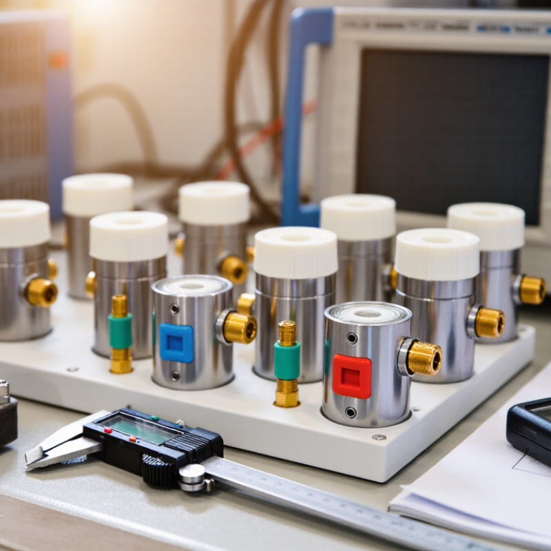
Define the filter’s operating window before comparing samples. Write down the lowest and highest frequencies, the wanted channel width, and nearby signals that must be rejected. Then set measurable limits for insertion loss, stopband attenuation, return loss, and group delay. A passband that looks wide enough on paper may still distort a narrow signal near its edge. Small details matter.
The FCC’s 2020 3.7 GHz Report and Order made 280 MHz of spectrum, from 3.7 to 3.98 GHz, available for flexible use. This is a useful reminder that real allocations can span broad bands, while individual systems use narrower channels. Specify both the overall tuning range and the exact passband needed in operation. Also state how far outside that passband rejection must begin; vague terms such as “high selectivity” are hard to verify.
Tip: Send suppliers a frequency table, not just a center frequency. Include operating temperature, input power, and the measurement method. Ask for test curves across the full band, including both passband edges. Compare the curves with your system limits, not only a single headline loss value. If the requirements are still uncertain, say so and request a tolerance review before production. It is an easy step to overlook.

A dielectric filter should be selected for the signal it must pass, not just its center frequency. Define the operating band and the frequencies that need rejection. A narrow channel may call for a sharper response, while a wider signal needs enough passband to avoid cutting off useful information. Small details matter. Check insertion loss, return loss, and rejection at specific offset frequencies, rather than relying on a single headline figure.
Consider the full system around the filter. Confirm its impedance, connector or mounting style, and available space; even a well-specified part can perform poorly when the layout or connections are unsuitable. Check expected input power and operating temperatures, too, since both can affect performance and long-term stability. If the filter sits near a transmitter, nearby strong signals may make out-of-band rejection especially important. Ask for measurement conditions and tolerance data, then compare them with your actual requirements. A specification sheet rarely tells the whole story. I still find it easy to overlook test conditions, so leave room for a bench check in the intended setup before committing to a design.
Example bandwidths for three common RF use cases
Check the required passband, insertion loss, rejection, impedance, power handling, and operating temperature before choosing a filter. GPS L1 C/A has an approximately 2.046 MHz null-to-null signal bandwidth; the 2.4 GHz ISM allocation spans 83.5 MHz, while the US 5.8 GHz ISM allocation spans 150 MHz. These are band references, not universal filter specifications; allow suitable margin and verify local regulations and system requirements.
Dielectric filters depend on more than their advertised frequency range. Ask what ceramic or other dielectric material is used, and how its temperature coefficient affects frequency stability. A small shift can matter in a narrow channel. Check the specified insertion loss and power handling at your actual operating frequency, not just at a convenient test point.
Look closely at construction. Resonator dimensions, metallization quality, solder joints, and enclosure sealing can all influence repeatability. Request drawings or tolerance information when the filter must fit a tight layout. Inspect how connectors are attached, too; a solid filter can still perform poorly if its interfaces are inconsistent. Details add up.
Environmental limits deserve equal attention. Compare the operating and storage temperature ranges with conditions inside the finished equipment, where heat may build up near power components. Check humidity, vibration, and thermal-cycle ratings if the device will face frequent temperature changes. Ask whether performance was measured across those conditions, and review the test limits rather than relying on a single pass result. Not always obvious. If the application sits near a limit, allow margin and verify performance in the assembled system. Specifications can look reassuring on paper; real installations are less tidy.
A supplier’s datasheet is a starting point, not proof of performance. Compare insertion loss, rejection, passband ripple, and temperature drift at the same frequencies and test conditions. Ask for measured plots, not only pass/fail statements. Check whether the sample was tested in a fixture that resembles your circuit. Small connector or launch differences can distort results. They matter.
Ask how the supplier controls lot variation and what records accompany each shipment. NIST Technical Note 1297 explains that expanded measurement uncertainty often uses a coverage factor of 2, corresponding to roughly 95% coverage under stated assumptions. NIST/SEMATECH’s e-Handbook gives the familiar normal-distribution reference: about 95% of observations fall within two standard deviations. These figures are useful context, not guarantees of filter yield. Request uncertainty, calibration status, and repeatability data for critical measurements. A polished report can still leave gaps.
For custom designs, provide a clear frequency range, allowable loss, rejection targets, power level, package limits, and operating temperatures. Then compare suppliers’ simulation, prototype, and verification plans. Ask what changes trigger retesting. I would challenge my own shortlist here: a fast prototype is tempting, but unclear acceptance criteria can create expensive surprises. Request a sample test plan before approving tooling or a production order. Keep the first review practical. Which measurement would make you reject the part?
When comparing dielectric filters, do not stop at unit price. Ask for a total-cost breakdown covering engineering, tooling, tuning, testing, shipping, and replacement lead time. Insertion loss can affect system-level costs by increasing gain or thermal requirements; check this against your link budget. Request measured S-parameters across the specified temperature range, not only a typical curve. Small detail. Big consequence.
Delivery deserves equal scrutiny. The World Bank’s 2023 Logistics Performance Index reports an average 44 days from export port to destination port, with a 10-day standard deviation. That is transit time, not factory production time. Ask suppliers to separate design approval, fabrication, inspection, and freight dates. Confirm what starts the delivery clock. McKinsey Global Institute’s 2020 analysis estimates that disruptions lasting a month or more occur every 3.7 years and can cost firms 45% of one year’s EBITDA over a decade. A buffer may be worthwhile when a missed integration slot is expensive.
Check support before purchase: response targets, failure-analysis turnaround, recalibration options, and access to test data. Put key commitments in writing. I would challenge vague promises such as “lifetime support.” Some teams may over-specify paperwork, too. Still, serial-level test records and a named technical contact can help isolate faults if a filter drifts after installation. Compare those commitments with the cost of holding a spare and the impact of downtime.
| Tip | What to assess | Practical checks | Why it matters |
|---|---|---|---|
| 1 | Confirm the electrical requirements | Specify center frequency, passband bandwidth, insertion loss, return loss, rejection requirements, and operating temperature. Ask for measured S-parameter data across the required frequency range. | A filter that misses the required frequency response may need redesign or additional components, increasing integration cost and delaying qualification. |
| 2 | Check power and environmental limits | Review maximum input power, temperature range, vibration or shock requirements, humidity exposure, and any applicable environmental test conditions. Confirm how performance changes over the specified range. | Thermal and mechanical conditions can affect frequency response and reliability. Limits should match the actual system environment, not just laboratory conditions. |
| 3 | Compare total cost of ownership | Include unit price, tooling or non-recurring engineering, qualification testing, connector or mounting options, shipping, import duties, inspection, and expected replacement or requalification costs. | The quoted unit price may not include setup, testing, logistics, or integration expenses. Comparing the full cost gives a more useful basis for supplier decisions. |
| 4 | Verify delivery time and capacity | Request separate estimates for engineering samples, qualification units, and production quantities. Ask whether lead time starts after specification approval, order acceptance, or material availability; confirm capacity and shipment schedule in writing. | Custom designs and production volumes can have different schedules. Clear milestones help identify schedule risk before it affects system integration. |
| 5 | Review testing and documentation | Confirm the acceptance test method, calibration traceability where required, production test coverage, and availability of a datasheet, outline drawing, test report, and material or compliance declarations relevant to the application. | Defined test criteria make incoming inspection and product qualification more consistent and help resolve performance questions later. |
| 6 | Assess ongoing technical support | Ask who handles design questions, tuning requests, failure analysis, and revision control. Clarify response channels, escalation process, warranty terms, repair or replacement procedures, and support availability after delivery. | Responsive support can shorten troubleshooting and change cycles, especially when the filter must be matched to a particular RF chain or enclosure. |
| 7 | Check supply continuity and change control | Discuss product lifecycle expectations, notice for design or material changes, availability of repeat orders, and options for approved alternates. Record the exact revision and configuration in the purchase specification. | Controlled revisions and continuity planning reduce the risk of unexpected fit, performance, or qualification differences between deliveries. |
Note: Lead times, pricing, test scope, and performance limits are specific to the design, order quantity, and application; confirm them with the supplier in a written quotation and specification.