How to Choose Low Frequency Filters in 2026
Choosing Low Frequency Filters in 2026 starts with a practical question: which signals must be reduced, and what must remain? A filter for a sensor near a motor may need to suppress hum without hiding slow temperature changes. An audio circuit faces a different balance. Its bass response, noise level, and available power all matter. The right choice depends on the signal, the circuit, and the conditions around them. There is no universal best filter.
This guide explains how to compare passive and active designs, set a suitable cutoff frequency, and check attenuation, impedance, and component tolerances. It also considers real installation details, such as cable length, nearby switching equipment, and limited board space. Small details matter. A filter that looks correct on paper may behave differently when connected to its source and load. That is easy to overlook.
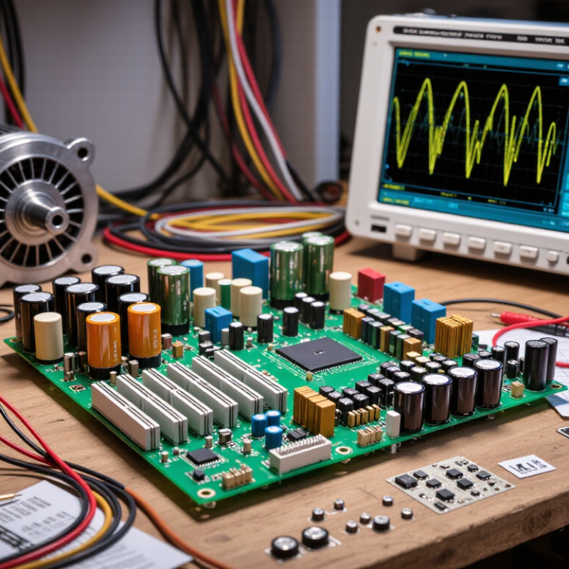
Use manufacturer datasheets and measured results where possible, rather than relying on a label or a single headline specification. For demanding systems, confirm performance across the expected frequency range and operating conditions. A simple test with a signal generator and oscilloscope can reveal unexpected ringing or loss. Yet measurements have limits, too; probes and wiring can influence what you see. This guide offers a careful framework for selecting a filter, while leaving room to question assumptions and verify the final design in its real application.
What Low-Frequency Filters Are and How They Work
A low-frequency filter shapes signals near the lower end of a system’s frequency range. It may preserve slow changes, reduce rumble, or separate bass information from higher-frequency content. The exact purpose matters: “low-frequency filter” can describe different responses. A low-pass filter passes frequencies below its cutoff and reduces those above it. A high-pass filter does the reverse, attenuating low frequencies while allowing higher ones through.
That distinction matters. Filters do not usually switch sharply at one precise frequency. Their response slopes gradually, and the cutoff is a reference point, not a brick wall. In a small audio circuit, for example, a capacitor and resistor can form a simple filter. Their values affect the cutoff, while the connected equipment’s input impedance can shift the result. Real circuits vary.
When choosing a filter, identify which frequencies should remain and which should be reduced. Check the cutoff frequency, attenuation slope, signal level, and expected load. A steep slope may suppress unwanted bass more strongly, but it can also affect nearby useful sounds. For vibration sensors, the relevant signal range may be much lower than for audio, so a familiar cutoff value may be unsuitable. Specifications help, but testing the filter with the actual source and load is still important. I’d treat calculations as a starting point, not a guarantee. Components drift, and the real response can be a little untidy.
Identify the Signals and Frequencies You Need to Filter
How to Choose Low Frequency Filters in 2026
Before choosing a filter, decide what the signal should do. Are you removing slow drift, keeping a bass range, or isolating gradual changes? These goals require different settings. A high-pass filter can reduce sensor offset, while a low-pass filter can suppress rapid noise and preserve slow movement. A band-pass filter can keep a defined frequency range. Check the signal itself: plot a representative recording and note where useful patterns and unwanted components appear. A vibration trace might show a steady wobble near 2 Hz, with sharp spikes from impacts. Do not choose a cutoff from habit. The right value depends on the signal and what you need to measure.
Tips: Write down the frequencies you want to keep and reject. Compare the filter’s cutoff and roll-off with those ranges. Test it on a short sample first. Look closely at the result.
Also check sampling rate and filter response. A steep roll-off can separate nearby frequencies, but may distort timing or create ringing. A gentler filter may preserve waveform shape better. If phase matters, inspect phase response as well as amplitude. There is no perfect setting; real signals can mix useful changes with noise. I would revisit the cutoff after testing against known examples, because one setting can look clean yet hide a meaningful detail. Keep the original data for comparison.
Compare Common Low-Frequency Filter Types
Choosing a low-frequency filter starts with the signal you want to keep. A low-pass filter reduces higher-frequency noise, while a high-pass filter removes slow drift or DC offset. A band-pass filter keeps a selected range, such as the tones around a sensor’s operating frequency. A notch filter targets one narrow interference band. Each choice changes the signal differently.
Filter response matters as much as filter type. A gentle slope may preserve waveform shape but leave more unwanted noise. A steeper slope gives stronger rejection, yet can introduce ringing or phase shift. Active filters use amplifiers and can provide gain; passive RC or LC designs need no powered amplifier but may load the source. Digital filters allow precise adjustment, though sampling rate and processing delay matter. A calculation is a useful start, not proof: real component tolerances and wiring can shift the cutoff.
Tips: Check the source and load impedance, then test with the actual signal. Look at the cutoff, slope, phase, and noise floor. If the result sounds or measures wrong, revisit the assumptions; a tidy design can still miss the mark.
Evaluate Key Specifications and Compatibility
How to Choose Low Frequency Filters in 2026
Evaluate Key Specifications and Compatibility
Start with the signal’s actual frequency range, not the filter’s label. Record the lowest and highest wanted frequencies, then set the cutoff with room for component tolerances and temperature drift. Check attenuation at unwanted frequencies, passband ripple, insertion loss, and impedance. A sharp cutoff may look ideal on a specification sheet, but it can distort signals near the passband edge. That part is easy to miss.
For cellular RF designs, 3GPP TS 38.104 Release 18 defines the FR1 range as 410 MHz to 7.125 GHz. This is a broad operating range, not a recommended filter passband. Match the filter to the specific band, source and load impedances, connector type, and circuit layout. In audio or sensor circuits, verify that the filter’s input impedance will not load the signal source. Check the datasheet’s test conditions, too; measurements made with different impedances may not predict your system’s performance. A paper match can still fail on a real board. Test the assembled circuit with the intended source and load, and inspect both the passband and stopband. I would leave margin.
Select, Install, and Test the Right Filter for 2026
In 2026, choose a low-frequency filter by defining the unwanted range, the signal level, and the load impedance. A filter’s cutoff is not a magic wall; attenuation changes gradually beyond it. Check the required roll-off and phase response before choosing a passive or active design. For power applications, IEEE 519-2022 sets an 8% voltage total harmonic distortion limit at the point of common coupling for systems rated 1 kV or less. That is a system-level benchmark, not a guaranteed filter setting. Measure the actual waveform first. Small details matter.
Install the filter close to the noise source, keep leads short, and follow the circuit’s grounding and shielding plan. De-energize equipment before wiring, and verify capacitor discharge where applicable. Then test with a signal generator and oscilloscope, or a power-quality analyzer for mains systems. Sweep below and above the chosen cutoff, recording attenuation and any unwanted resonance. Compare power-system harmonic readings with the applicable IEEE limits; a compliant reading does not prove every sensitive device is protected. I would recheck under the real load, because bench results can be too neat. That part is easy to miss.
How to Choose Low-Frequency Filters in 2026
Compare the theoretical frequency responses of first-, second-, and fourth-order Butterworth low-pass filters with a 100 Hz cutoff. A steeper roll-off can reduce out-of-band signals more quickly, while filter order can also affect phase response and implementation complexity.
How to use this chart: Choose a cutoff that preserves the frequencies you need, then check the required attenuation, phase behavior, and practical constraints for your application. These curves represent ideal Butterworth responses; real filters may differ.