Why Choose Waveguide Filters for RF Applications?
As RF systems move into higher frequency bands, filtering becomes a physical design problem, not just a schematic choice. Waveguide Filters offer low-loss transmission, strong power handling, and sharp frequency selectivity—useful traits in satellite payloads, radar front ends, and high-capacity microwave links. MarketsandMarkets’ RF filters market report projected growth from about $12.5 billion in 2023 to $17.5 billion by 2028. That figure covers RF filters broadly, not waveguide filters alone, but it reflects rising demand for precise frequency control.
David M. Pozar’s Microwave Engineering describes a filter as a network that passes desired frequencies and attenuates others. That is the core task. A waveguide implementation can make sense when a design needs low insertion loss at microwave or millimeter-wave frequencies, or must handle substantial power. Inside a carefully machined cavity, the resonant dimensions help define the passband. Small manufacturing errors still matter.
The benefits are not automatic. Size, cost, assembly tolerances, and bandwidth requirements can make other filter technologies more practical. One detail is easy to overlook: a low-loss filter cannot compensate for a poorly matched transition or a rough integration plan. Engineers should compare measured insertion loss, return loss, rejection, power capacity, and temperature stability against the complete system requirements. The best choice depends on the application—and sometimes the first design is not the best one.
Waveguide filters shape RF signals by passing chosen frequencies and rejecting unwanted ones. A hollow metal channel confines electromagnetic energy, while its dimensions and internal features determine which wavelengths travel efficiently. Cavities, irises, and other structures create frequency-selective responses. The result can be a clean passband for radar, satellite links, or microwave test equipment. That matters. Compared with many planar filters, waveguide designs can offer low signal loss and handle substantial power, though size and manufacturing complexity may increase.
Tips: Check the operating band, power level, insertion loss, and rejection requirements before selecting a filter. Allow for connector transitions and installation space. Measure performance in the assembled setup; nearby components can affect the response.
A filter’s sharp cutoff may seem ideal, but real systems involve trade-offs. Narrow bandwidth can improve selectivity while making tuning and alignment more sensitive. Temperature changes and machining tolerances may shift performance slightly. One detail is easy to overlook: a specification measured under ideal conditions may not match a crowded equipment rack. Careful testing helps reveal that gap. Waveguide filters are not automatically the best choice for every RF path, but they can be highly effective when low loss, power handling, and frequency control outweigh their physical size.

A waveguide filter selects frequencies through its physical geometry, not merely through a circuit setting. In a rectangular guide, the broad-wall dimension sets the TE10 mode’s cutoff frequency: fc = c/(2a). For a 22.86 mm broad wall, the calculated cutoff is about 6.56 GHz. IEC 60153-2 specifies standard rectangular-waveguide dimensions, while IEEE Std 521-2019 defines X-band as 8–12 GHz. These figures help explain why a common WR-90 guide operates above cutoff, across roughly 8.2–12.4 GHz. The gap between cutoff and operating band matters.
Inside a filter, irises and cavity lengths shape the passband. Their spacing sets resonant frequencies; their openings influence coupling and bandwidth. Add more resonators, and the transition from passband to stopband can become steeper, though insertion loss and size may rise. Tiny changes matter. A small machining error can shift resonance, especially in narrow-band designs. Real hardware drifts. Temperature, surface finish, joints, and tuning screws all affect measured response. Ideal simulations are useful, but they do not capture every assembly detail. That limitation deserves attention during testing. Comparing measured S-parameters with the design model reveals where geometry, materials, or assembly have changed the filter’s frequency response.
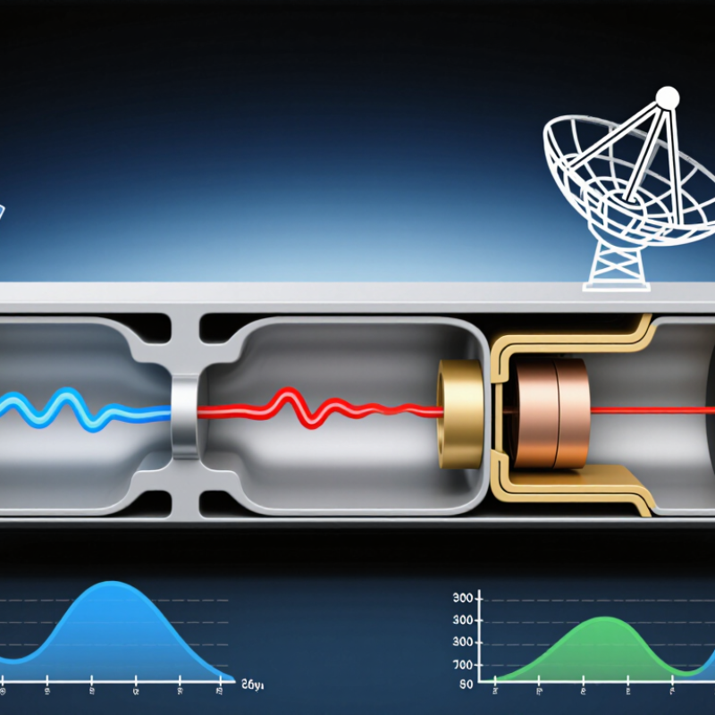
Illustrative band-pass response showing how waveguide dimensions can be tuned to select a frequency range while attenuating frequencies outside it. Values are representative, not measured product data.
How geometry helps: Waveguide dimensions determine resonant behavior and cutoff frequencies. Carefully designed cavities and coupling sections shape the passband and out-of-band rejection for the intended RF application.
Key Performance Advantages in High-Frequency RF Systems
At high frequencies, waveguide filters can provide low insertion loss and strong rejection of unwanted signals. Their hollow, conductive structures guide electromagnetic energy with limited resistive loss. This can help preserve signal strength in radar, satellite, and microwave test systems. The benefit depends on frequency, materials, surface finish, and design. Small manufacturing differences matter.
Waveguide cavities can also handle substantial power and support sharp filtering around selected frequency bands. Their enclosed geometry helps limit radiation leakage and external interference. That matters. They are not always the easiest option: compared with some planar filters, they may be larger, heavier, and more difficult to integrate. Their narrow passbands can also require careful tuning.
RF filter technologies solve different problems. Waveguide filters are most relevant when a design operates at microwave or millimeter-wave frequencies and needs low insertion loss, high selectivity, or substantial power handling. Their enclosed metal paths can support high-Q resonances, while carefully machined irises and cavities shape the passband. They are not magic. Their size, weight, cost, and mechanical tolerances can make them a poor fit for compact, low-cost equipment.
A microstrip filter often suits a lightweight board with tight space and modest power, though conductor and substrate losses may matter at higher frequencies. Coaxial and cavity filters can offer useful alternatives where adjustable tuning or a smaller assembly is important. Dielectric filters may provide compact, high-Q performance in some systems.
The right comparison depends on frequency, bandwidth, loss, power, temperature, and available volume—not a single headline specification.
In a radar front end or satellite link, a waveguide filter may protect a sensitive receiver while handling strong nearby signals. Engineers should check flange alignment, surface finish, thermal expansion, and transitions to coaxial or planar circuitry. A measured filter can also behave differently once installed in its housing. That detail is easy to overlook. A useful review compares simulated and measured responses, then asks whether the added size and assembly effort solve a real system problem. Sometimes the more elegant choice is not the most practical one.
Matching a waveguide filter begins with the signal, not the catalog. Define the center frequency, occupied bandwidth, and unwanted signals that need rejection. Then set measurable limits for insertion loss, passband ripple, and stopband attenuation. Small trade-offs matter. A tighter passband can improve selectivity, but may increase loss or complicate tuning.
Frequency determines the waveguide size and operating band. IEEE Std 1785.1-2012 specifies frequency ranges and dimensions for rectangular metallic waveguides; the commonly used WR-90 band spans 8.2 to 12.4 GHz. Treat that range as a starting point, not a complete specification. Check the filter’s actual passband against the transmitter or receiver channel, including frequency drift. A few megahertz can matter in a narrow channel.
Next, match the hardware to the installation. Compare peak and average power, flange type, allowable temperature range, vibration, and moisture exposure. In a rack-mounted receiver, for instance, a filter may meet its lab response yet detune after heating or poor flange alignment. Ask for measured S-parameters across the operating band and under relevant conditions. Data sheets do not always show the whole story. Specify how measurements were taken, and leave margin for cables, joints, and manufacturing variation.